
Have a query or want to arrange for sales assistance?
Contact us now by filling out the form or drop us an email. And we’ll get back to you as soon as possible.
In an underground high voltage cable system, the conductor carries the main load current. However, the metallic sheath surrounding the cable also experiences electromagnetic effects.
Voltage can be induced in the metallic sheath as current flows through the conductor. If the sheath bonding system is not designed correctly, unwanted sheath current, additional losses, heating, and potentially unsafe sheath voltage can occur.
Link boxes help engineers control these conditions.
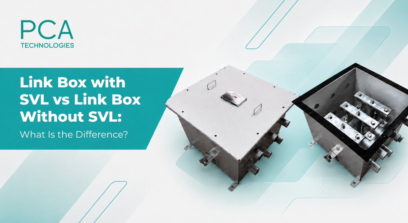
A link box provides an accessible location where cable sheaths can be connected, disconnected, earthed, or cross connected according to the selected bonding arrangement. Depending on the cable system design, engineers may specify a link box with SVL or a link box without SVL.
The difference is important because a Sheath Voltage Limiter performs a specific protective function.
Before comparing Link Boxes with and without SVL, it is necessary to understand sheath bonding.
Single core HV cables generally contain a metallic screen or sheath around the insulation. The magnetic field produced by conductor current induces voltage along this metallic layer.
How this voltage behaves depends strongly on the bonding arrangement.
Common arrangements include solid bonding, single point bonding, and cross bonding. Link boxes provide removable connections that allow these sheath circuits to be configured according to the bonding design. They also make sheath testing and maintenance easier because individual connections can be opened when required.
The internal copper connections inside the box therefore cannot be selected independently. Their arrangement must correspond with the cable system sheath bonding diagram.
A link box with SVL includes one or more Sheath Voltage Limiters.
An SVL is a nonlinear protective device used to control temporary or transient voltage appearing on a cable sheath. Metal oxide technology is commonly used for this purpose. Under normal operating conditions, the SVL remains effectively non conducting at the expected sheath voltage.
When sheath voltage rises beyond its designed protective level, the SVL begins conducting and provides a path for surge current. This limits the voltage stress applied to the cable oversheath, sectionalizing insulation, joints, and connected equipment.
Transient sheath voltage can arise during events such as switching operations, lightning disturbances, or faults.
The SVL therefore acts as a protective clamp.
It is important to understand that the SVL itself is not the primary method used to eliminate normal circulating sheath current. Circulating current is mainly controlled through the selected sheath bonding arrangement. The SVL protects the insulation system when sheath voltage rises beyond acceptable conditions.
A link box without SVL contains the necessary links and connections for sheath bonding but does not include a Sheath Voltage Limiter.
This does not mean that the link box is incomplete or inherently less safe.
Whether an SVL is required depends on the bonding design, box location, cable section length, earthing configuration, expected sheath voltage, insulation withstand level, and system study.
For example, certain directly earthed locations may not require an SVL because the metallic sheath is intentionally connected to earth through a low impedance path.
A link box without SVL can still provide disconnectable links for testing, straight bonding, cross bonding, or other project specific sheath connections. Commercial link box ranges include configurations both with and without SVLs for different positions within the cable bonding arrangement.
The practical differences can be summarized as follows.
Design Point | Link Box with SVL | Link Box without SVL |
Sheath connections | Yes | Yes |
Disconnectable links | Normally provided | Normally provided |
Surge voltage limitation | Yes | No internal SVL |
Used in bonding schemes | Yes | Yes |
Protection against excessive transient sheath voltage | Provided by SVL | Must be addressed elsewhere in system design |
Selection basis | Bonding study and sheath voltage | Bonding study and earthing arrangement |
This comparison shows why the decision should not be based only on cost.
The key engineering question is whether the sheath insulation can safely withstand the calculated voltage under normal, fault, and transient conditions.
A 3 phase link box with SVL manages sheath connections associated with the three single core phase cables in a circuit.
Its internal arrangement depends on whether the installation uses straight bonding, single point bonding, cross bonding, or another engineered configuration.
Cross bonding provides a useful example.
A long cable circuit can be divided into sections. At selected sectionalizing joints, the sheath connections of the three phases are transposed through link boxes. The objective is to balance the induced sheath voltages over the complete major section and reduce undesirable circulating currents and associated sheath losses.
SVLs may be installed at selected points where the sheath must remain insulated from earth during normal operation but requires protection against excessive transient voltage.
A 3 phase link box with SVL can therefore perform two related functions. It provides the required sheath interconnections and gives the bonding system a controlled protective path when sheath voltage exceeds the selected SVL level.
Consider a long underground HV cable circuit between two substations.
If the sheaths were bonded to earth at both ends of every cable section without proper engineering, circulating sheath current could increase losses and cable heating.
The designer may therefore divide the route into sections and use cross bonding.
At sectionalizing locations, link boxes provide the required cross connections. SVLs can be connected where the bonding design leaves a sheath electrically insulated from direct earth under normal conditions.
At another location where the sheath is solidly bonded to earth, a link box without SVL may be appropriate.
This example demonstrates an important rule: one cable route may contain both types of link boxes.
Selection should begin with the cable bonding study rather than the link box catalogue.
Engineers should evaluate cable voltage, route length, conductor current, sheath construction, bonding arrangement, earth resistance, fault current, expected induced voltage, transient conditions, and sheath insulation withstand capability.
The location of each link box must then be matched with the sheath bonding diagram.
A link box with SVL provides important transient voltage protection where required. A link box without SVL provides the necessary sheath connections where direct surge limiting inside the box is not required.
Both can form essential parts of a properly engineered HV cable system.
Looking for the right link box configuration for your HV cable project? Contact PCA Technologies for technical support and cable solutions.
An SVL limits excessive voltage appearing on the cable metallic sheath. It conducts during abnormal voltage conditions and helps protect the sheath insulation and related cable accessories.
A link box with SVL includes protective devices that limit excessive sheath voltage. A link box without SVL provides sheath bonding and disconnectable connections without internal surge voltage limiting.
No. SVL requirements depend on the sheath bonding scheme, cable length, box location, earthing system, calculated sheath voltage, and insulation withstand level.
A 3 phase link box with SVL provides sheath connections for the three phase cables and incorporates SVLs where surge limitation is required by the bonding system design.
Link boxes are commonly installed near cable terminations, insulated joints, sectionalizing points, and cross bonding locations. Their exact position is determined by the cable sheath bonding design.
Contact us now by filling out the form or drop us an email. And we’ll get back to you as soon as possible.
© PCA Technologies Private Limited – 2026